

 English
 中文简体
 русский
 Español


Industry News
 +86-13306862930 / +86-18668881826
Get a Quote
+86-13306862930 / +86-18668881826
A helical gear can resemble a spur gear at a glance, yet the tooth direction changes how it engages with its partner. The teeth run at a slant across the gear face instead of lying parallel to the shaft. That slant is the helix angle, and measuring it tells manufacturers about tooth direction, gear geometry, and how mating parts relate. When checking a Helical Rack Gear or a Helical Rack Pinion, the angle also explains how the teeth are meant to engage during movement.
Holding a ruler against a tooth will not give a reliable answer. The result depends on the reference direction, the gear dimensions, and the method chosen. A clear process cuts down reading errors and keeps inspections consistent.
The measurement comes up in product development, machining inspection, quality checks, and replacement-part selection. It also helps tell helical gears apart from straight-tooth designs such as a Spur Gear Rack and Pinion. Once the basic geometry is clear, the process is easy to follow, even for people who rarely inspect gears.
The helix angle describes the direction of a tooth relative to the gear axis. Look at a cylindrical gear from the side, and the teeth do not run straight along the axis. They follow a slanted path around the body.
That slant forms the helix angle. It is usually taken between the tooth direction and a line parallel to the gear axis, on the appropriate cylindrical reference surface.
The angle shapes how teeth meet during rotation. Because the tooth is inclined, contact builds gradually across the face, unlike the engagement of a straight-tooth gear.
A change in the helix angle alters tooth orientation and the forces produced in operation. For that reason, the figure matters when checking whether two parts are designed to work together.
Choose the correct reference before measuring. An angle read from the tooth trace in a side view may not match one taken from another viewing direction, so the inspection method should state which reference applies.
Helix angle is tied closely to gear compatibility. Two helical gears meant to mesh need matching tooth directions and related geometry. A wrong reference or an unsuitable method can lead to a false assessment.
In production, the angle confirms whether the tooth form follows the design. If the direction differs from the intended geometry, the gear may not engage as expected, which can affect contact distribution, movement, and operating sound.
Replacement work benefits too. A new gear may match the old one in size and shape yet carry a different tooth direction. Checking the angle avoids choosing a part on outward appearance alone.
Rack-and-pinion systems add another layer. A Helical Rack Pinion is built to work with a compatible helical rack, whereas a Spur Gear Rack and Pinion uses straight teeth and a different engagement arrangement. Comparing the two shows why tooth direction should be checked, not assumed.
The table below lists common reasons for measuring the angle.
| Inspection Situation | Why the Measurement Matters |
|---|---|
| New gear production | Checks whether the tooth direction matches the design |
| Incoming component inspection | Helps verify the supplied gear geometry |
| Replacement part selection | Reduces the risk of choosing an incompatible component |
| Gear pair evaluation | Supports checks of mating tooth direction |
| Product development | Helps compare different gear arrangements |
| Quality control | Provides a reference for inspection records |
Treat the angle as one item among several gear dimensions. A suitable helix angle alone does not show that a gear is ready for use, since tooth spacing, profile, and mounting arrangement also affect compatibility.
The right tool depends on gear shape, the detail required, and the equipment on hand. Some methods suit a quick workshop check, while others fit detailed manufacturing inspection.
A simple angle tool works when the tooth trace is visible and within reach. The gear surface is curved, though, so a suitable reference is needed. Pressing a standard tool against an unsuitable surface can give a misleading reading.
Optical measurement makes the tooth direction easier to inspect. The trace can be viewed and compared with a reference line, which helps with small teeth or when touching the surface is undesirable.
A gear measuring instrument assesses tooth geometry through a controlled process. Factories often use it where consistent results and inspection records matter.
A coordinate measuring machine collects points from the gear surface, and those points define the tooth direction for calculating the angle. This calls for careful planning and a clear grasp of the reference geometry.
| Tool or Method | Suitable Use | Main Consideration |
|---|---|---|
| Angle measuring tool | Basic visual or workshop checks | Requires a clear reference line |
| Optical measurement | Viewing the tooth trace | Surface visibility affects the reading |
| Gear measuring instrument | Detailed gear inspection | Requires suitable setup and calibration |
| Coordinate measuring machine | Geometric inspection using measured points | Measurement points must represent the tooth direction |
| Digital image analysis | Examining a visible tooth trace | Image alignment and scale need attention |
Check the condition of any instrument before use. A damaged, misaligned, or ill-suited tool gives unreliable results. Pick the method to match the inspection need, not just because the equipment is nearby.
Manual measurement works when the gear is accessible and the tooth trace is easy to identify. It often serves for preliminary checks or when specialized equipment is unavailable.
The aim is to establish the gear axis and view the tooth direction from a suitable position. The angle taken should relate to the same reference used in the design.
Keep the gear steady throughout. Movement shifts the apparent tooth direction and makes alignment difficult.
A frequent mistake is measuring from the wrong viewing direction. The visible tooth line looks different when the gear is rotated or seen from another side, so use a defined reference rather than eyeballing the angle.
Surface condition matters as well. Burrs, worn teeth, and damaged edges hide the tooth direction. When the trace is unclear, an optical or instrument-based method may give a more dependable reading.
The angle can also come from known gear geometry. This works when the relevant dimensions are available and their relationship is understood.
On a helical gear, the tooth direction forms a slanted path around the cylindrical body. The angle connects to the gear diameter and the distance the tooth trace travels along the circumference.
A simplified approach uses the circumference at a chosen reference diameter and the axial distance over which the trace completes its matching turn. Unwrap the cylindrical surface, and these dimensions form a right triangle.
The basic relationship is:
tan β = πd / L
Where:
Applying the inverse tangent gives the angle:
β = arctan (πd / L)
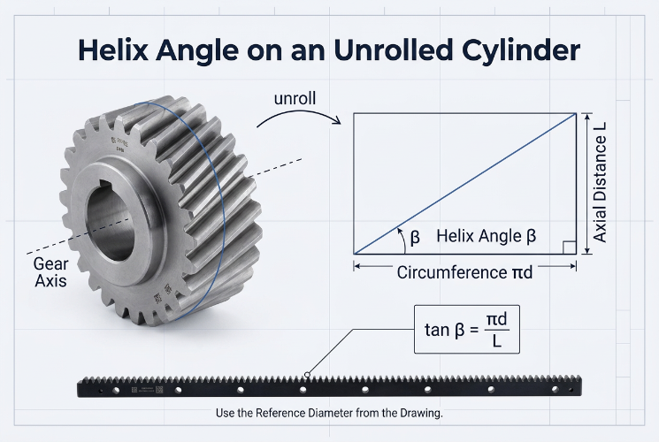
This relationship shows the geometry of a helix. Check how the dimensions are defined before applying it, because drawings may use different reference diameters and conventions, and the measurement must match the specified geometry.
Another way to picture it: cut the cylinder along its length and lay it flat. The curved tooth trace becomes a slanted line, and its angle to the axial direction relates to the two sides of the triangle that results.
Calculation helps when reviewing a drawing or a gear design. It relies on accurate dimensions, though, so an error in the reference diameter or axial distance carries straight into the calculated angle.
Even a simple method can go wrong in several ways. Knowing the usual problems helps inspectors avoid readings that seem reasonable but do not reflect the real geometry.
The angle must be taken against the intended reference line. Measuring from a line perpendicular to the axis, instead of one parallel to it, gives a different angle relationship.
A helical tooth follows a curved path around the body. Measurements on different cylindrical reference surfaces may not be interchangeable, so the diameter should match the drawing or inspection standard.
Worn edges, burrs, and scratches obscure the tooth trace. Look over the measurement area before assessing the angle.
An unstable gear shifts while the tool is being aligned. Secure positioning keeps the reference consistent.
A tooth can seem to have a certain inclination from an oblique view, but perspective alters its apparent direction. A defined method is more dependable than judging by eye.
An instrument may not fit the gear size, tooth form, or surface condition. Confirm its alignment and calibration before use.
A good inspection record names the method and reference used. Another inspector can then see how the result was reached and compare it with the design information.
The idea of inclined teeth carries over to helical rack-and-pinion systems. A cylindrical gear and a linear rack do not share the same geometry, however, so each needs its own measurement reference.
A Helical Rack Gear has teeth set at an angle along the rack. Paired with a compatible pinion, the inclined direction produces progressive contact as the parts move, unlike a straight-tooth arrangement.
A Helical Rack Pinion is made to engage a matching helical rack. Its tooth direction and related geometry must suit the rack design. Inspectors should look at the relationship between pinion and rack rather than judge the pinion angle on its own.
A Spur Gear Rack and Pinion uses straight teeth, with rack teeth running across the rack in a direction that differs from the inclined layout of helical designs. This difference matters when selecting replacement parts or reviewing drawings.
| Gear Arrangement | Tooth Direction | Inspection Focus |
|---|---|---|
| Helical gear | Inclined around the gear body | Helix angle and reference diameter |
| Helical rack | Inclined along the rack | Tooth direction and matching pinion |
| Helical rack pinion | Inclined around the pinion body | Compatibility with the rack |
| Spur gear rack and pinion | Straight tooth arrangement | Tooth alignment and spacing |
Do not treat the helix angle as the only factor in a rack-and-pinion inspection. Tooth spacing, contact condition, mounting alignment, and the intended direction of movement also deserve attention.
For manufacturers, clear drawings and steady inspection references reduce mix-ups between helical and spur products. Purchasing and engineering teams can then identify the required parts more easily.
A consistent process starts before the gear reaches the measuring station. The drawing should state the angle reference and the geometric information needed for checking, so inspectors apply the same approach throughout production.
Manufacturers can also set inspection stages. A preliminary check may catch visible tooth-direction problems, while a detailed measurement confirms the geometry of the finished part. The method should reflect the product design and its application.
Measurement tools need regular attention. Clean surfaces, stable fixtures, and proper calibration reduce avoidable variation. Inspectors also need clear instructions on positioning the gear and identifying the reference direction.
Records should hold enough information to make the result understandable, such as part identification, method, reference surface, and outcome. They support production review and communication between manufacturing and quality teams.
For companies producing gears and transmission components, inspection ties closely to product consistency. A clear process reveals differences between the design and the finished part before assembly or delivery.
If your project involves helical gears, rack-and-pinion assemblies, or customized transmission components, contact our team to discuss your drawings, gear structure, and inspection requirements. Sharing the intended application and relevant design information helps us understand your needs and explore suitable manufacturing and quality-control arrangements.

© 2025 Zhejiang Yuchen Transmission Technology Co., Ltd.

Transmission Gear And Rack


