

 English
 中文简体
中文简体 русский
 Español

Industry News
 +86-13306862930 / +86-18668881826
Get a Quote
+86-13306862930 / +86-18668881826
Helical gear rack and pinion systems often look simple in structure, yet installation quality decides how the whole motion behaves during operation.
A small deviation during mounting does not stay small once motion begins. Gear teeth gradually translate that small error into uneven contact. Over time, movement becomes less smooth, and load begins to concentrate on limited tooth areas.
Helical structure introduces another layer of sensitivity. Because tooth engagement happens in a slanted contact pattern, axial force appears during rotation. When alignment is not stable, that force does not distribute evenly.
Field observation often shows a pattern:
helical gear rack and pinion systems respond strongly to initial positioning quality, since every later adjustment follows that first alignment path.
Before placing any rack segment, mounting surface condition decides whether alignment work will remain stable or continuously drift.
A flat surface does not only mean visually straight. It refers to consistent contact behavior along the full mounting length.
Common conditions checked in practice include:
Even small debris between rack and base can create uneven height distribution. That unevenness later appears as tooth misalignment during rotation.
helical gear rack and pinion alignment begins from surface behavior rather than gear engagement itself.
During preparation, installation area often receives repeated cleaning and dry inspection. Some technicians pass a straight reference edge across mounting zone just to observe light gaps.
A stable base allows rack alignment to remain predictable during tightening sequence.
Initial placement of rack sets the direction for all later alignment work. Once fixed incorrectly, correction becomes more difficult during final meshing stage.
Rack is usually placed lightly on mounting surface. Fixing screws are inserted, though not fully tightened. Slight movement remains possible at this stage.
Gauge pins or measuring tools help define initial height reference. Rack teeth must sit at consistent elevation across full length.
A typical positioning sequence often follows natural progression:
Center-first positioning reduces cumulative error. Starting from one side often allows small deviation to propagate along the full length.
helical gear rack and pinion systems rely heavily on this early stage because later adjustment range becomes limited once full tightening is applied.
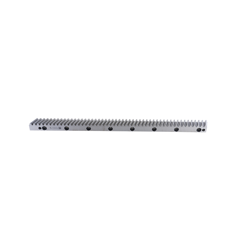
Height adjustment controls how gear teeth meet during meshing. Even small differences in vertical position change contact behavior across tooth surfaces.
Parallelism between rack and motion axis affects whether load distributes evenly or concentrates in one region.
Adjustment often involves repeated checking rather than single measurement. Dial indicators or similar tools are moved along the rack to observe height consistency.
Typical observation pattern during adjustment:
helical gear rack and pinion performance depends on maintaining uniform height across entire length.
If one end sits slightly higher, gear contact shifts diagonally, producing uneven wear over time.
Fixing process influences whether earlier alignment remains stable or gets distorted.
Tightening all screws at once often introduces stress inside rack body. That stress may slightly bend mounting position, even when change is not visible.
A more stable pattern usually follows staged tightening:
This sequence allows internal stress to distribute gradually instead of concentrating in one direction.
Dowel pins may be added after alignment confirmation. They help maintain position over long operation cycles.
During this stage, helical gear rack and pinion alignment can shift slightly if tightening order is not controlled.
Long travel systems often require multiple rack segments connected end to end.
At connection points, even small pitch mismatch creates noticeable vibration during motion. Alignment at these joints becomes critical.
Segments are usually placed in a butt joint configuration. A temporary guide piece or short rack segment is sometimes used across the joint to maintain continuity.
Key observation points include:
| Check Area | Observation Goal | Common Issue |
|---|---|---|
| Joint contact | Smooth transition | Step difference |
| Tooth pitch | Continuous spacing | Misalignment gap |
| Height level | Same elevation | Vertical offset |
| Movement test | No interruption | Micro vibration |
After rack sections sit in a stable position, attention naturally moves to the pinion side. At this point, small adjustments begin to matter more than structural changes.
Pinion is usually mounted in a way that still allows slight movement. Center distance is not fully locked. That small freedom helps during meshing adjustment.
When rotation starts slowly, contact marks begin to appear on rack teeth. A thin layer of marking compound is often used so contact position becomes visible.
What usually appears during observation:
Adjustment is done in small steps. Each small change in center distance affects how tooth surfaces touch along the helical path.
helical gear rack and pinion behavior becomes easier to read at this stage because real contact begins to show alignment quality.
Backlash is not fully removed in real operation. A small clearance usually remains to allow smooth movement during load changes.
Adjustment starts from center distance. Moving pinion closer reduces gap, moving it away increases it.
During adjustment, motion feedback becomes important:
In systems using dual pinion layout, one side may apply light preload. That helps reduce directional play during movement.
helical gear rack and pinion performance depends heavily on keeping clearance stable across full travel, not only at one position.
Slow rotation tells more than static inspection. Once motion begins, hidden alignment issues start to appear.
At low speed, movement should feel steady. No sudden change in resistance should be noticeable along the travel path.
During observation, typical signs include:
When binding happens, it rarely stays in one place. It often appears at repeatable positions, especially near segment joints or slight height mismatch areas.
helical gear rack and pinion systems expose these issues clearly once full mechanical contact is active.
Full travel testing gives a broader picture than local inspection.
When carriage moves across entire rack length, small differences begin to show up. Some sections feel smoother, others slightly heavier.
Typical field behavior:
| Travel Area | What Is Felt | What It Usually Means |
|---|---|---|
| Start zone | Smooth entry | Stable alignment |
| Middle zone | Even motion | Good meshing balance |
| Joint area | Slight change | Minor mismatch tolerance |
| End zone | Stable finish | System continuity maintained |
helical gear rack and pinion alignment quality often becomes clearer during this full stroke movement than during any single inspection point.
Lubrication quietly affects how the system feels during motion. At the beginning, movement may feel dry or slightly rough until lubricant spreads evenly.
Once distributed, contact between teeth becomes smoother. Sound level also becomes more stable during repeated cycles.
Common observations:
Uneven lubrication can create zones where movement feels different along the same rack. That is often mistaken for alignment issue, although sometimes it is only surface coverage difference.
helical gear rack and pinion systems rely on continuous lubrication film to maintain stable contact behavior.
After running for some time, installation state does not remain completely static. Small changes slowly appear due to repeated load cycles.
Fasteners may relax slightly. Contact surfaces begin to polish where load is higher. Some zones carry more wear than others.
Common long-term changes:
Regular checks usually focus on:
helical gear rack and pinion systems stay stable longer when these small shifts are noticed early and corrected before they grow.
After installation and several movement cycles, system behavior becomes easier to read. Smooth sections feel almost continuous, while problem areas show themselves through resistance or slight vibration.
helical gear rack and pinion performance is never decided by a single adjustment step. It comes from a chain of small decisions—surface condition, positioning, meshing, and how carefully each stage is checked during real movement.
Over time, the system reflects the quality of those early steps through how quietly and steadily it keeps running.

© 2025 Zhejiang Yuchen Transmission Technology Co., Ltd.

Transmission Gear And Rack


