

 English
 中文简体
中文简体 русский
 Español

Industry News
 +86-13306862930 / +86-18668881826
Get a Quote
+86-13306862930 / +86-18668881826
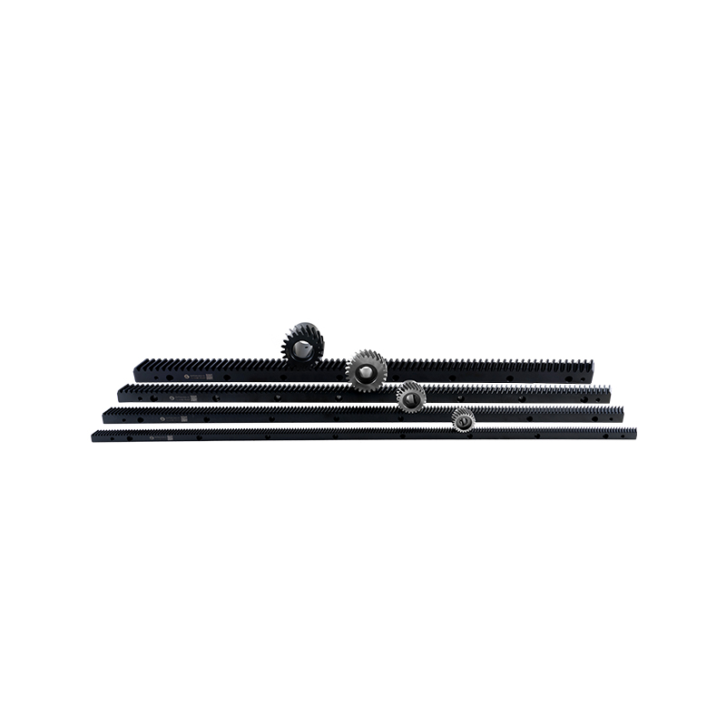
Load capacity is not one simple number you can look up on a chart. Many things come together to determine what a helical gear rack and pinion can actually handle out in the field. The geometry itself makes a difference right from the start. Helical teeth engage gradually rather than slamming together like straight-cut spur gears. That gradual engagement changes how forces spread across the tooth faces.
The angled tooth orientation puts multiple teeth in contact at any moment. More teeth sharing the load means less stress on each one. Contact ratio for helical designs runs higher than what spur gears achieve. Higher contact ratio gives better load distribution and smoother operation.
Two different capacity ratings exist—static and dynamic. Static rating covers steady, non-moving conditions. Dynamic rating applies when everything is moving. Dynamic capacity generally comes in lower because moving loads bring in acceleration forces, vibration, and other complicating factors.
A few points worth keeping in mind:
Tooth geometry drives how loads distribute across the gear. Helical angle determines engagement smoothness. Larger angles give more tooth overlap but push the gear sideways. That sideways force needs bearings designed to handle it.
Face width—the dimension across the gear—directly affects capacity. Wider teeth mean more contact area. More area lowers stress per unit of surface. Wider faces bring their own problems though. Alignment becomes harder. Misalignment has a bigger effect because there is more tooth length to get things wrong.
Designers make modifications to tooth profiles for real-world conditions. Slight crowning or tip relief compensates for deflection under load. Without these modifications, tooth ends carry too much stress as the gear bends slightly during operation.
Surface hardness preserves geometry under repeated loading:
| Design Feature | Effect on Load Capacity | Practical Consideration |
|---|---|---|
| Helical angle | Smoother engagement, higher contact ratio | Creates axial thrust that needs bearings |
| Face width | More contact area, lower stress | Wider faces demand careful alignment |
| Profile modification | Compensates for deflection | Improves real-world load distribution |
| Surface hardness | Resists wear and deformation | Must balance hardness against toughness |
The material you choose decides what the gear can withstand before failure. Steel dominates power transmission applications. Through-hardening gives uniform hardness all the way through the tooth. Case-hardening provides a hard shell over a tougher interior.
Toughness matters for shock loads. A sudden impact sends stress through the tooth structure. Tough materials absorb that energy without cracking. Hard materials resist surface wear but may fracture under unexpected impacts.
Some practical material considerations:
Wear resistance becomes critical when cycles add up. Each tooth contact removes microscopic amounts of material. Over time, wear accumulates and changes tooth geometry. Changed geometry affects load distribution and reduces effective capacity.
Installation quality determines whether you get the rated capacity or something lower. Alignment errors cause uneven load distribution. One side of the tooth carries more stress than the other side. That uneven loading reduces effective capacity below what the material could otherwise handle.
Misalignment shows up as uneven contact patterns across the gear face. Contact shifts to one edge of the tooth. Force concentrates in a small area instead of spreading across the full face. Localized overload leads to premature wear and pitting.
Support bearings influence system rigidity too. Bearings that allow deflection let the pinion move relative to the rack under load. That movement changes how teeth engage. Housing rigidity matters as well. Flexible housings allow gear centers to shift, altering the designed contact pattern.
A few things to check during installation:
Speed affects capacity through several channels. Higher speeds increase the frequency of tooth contacts. That frequency changes how quickly stress cycles accumulate toward fatigue failure. Speed also affects lubrication conditions—the oil film thickness changes with speed.
Vibration adds dynamic stress that static calculations miss. External vibration transmits through the system and adds to the transmitted load. The gear sees higher peak stresses than average load calculations would suggest.
Acceleration and deceleration create transient loads. Moving a mass requires extra force beyond what steady motion needs. That extra force shows up as a load peak. Rapid reversals produce even more severe transients.
Dynamic loading observations from field experience:
Oil film thickness supports the load between tooth surfaces. A thick film keeps metal surfaces separated. Separated surfaces experience lower friction and less wear. Elastohydrodynamic conditions—where the oil film deforms under pressure—let gears carry heavier loads than simple theory predicts.
Oil selection depends on application conditions. Different viscosities perform differently at various temperatures and speeds. A Helical Gear Rack Factory usually provides specific oil recommendations based on the application. Those recommendations consider load, speed, temperature, and expected service life.
Lubrication frequency affects performance. Too little oil allows boundary lubrication where surfaces touch. Boundary conditions increase wear rates and reduce effective load capacity. Contamination introduces abrasive particles that accelerate wear. Clean oil and proper maintenance protect gear surfaces from premature wear.
Theoretical load ratings assume perfect conditions. That is not how things work out in the field. Duty cycle matters because gears do not run continuously under identical loads. A system that sees heavy loads only occasionally can often be sized more aggressively than one that runs near capacity day in and day out.
Heat changes how materials behave. Steel gets softer as temperature climbs. That softening means the gear cannot carry as much load when hot as when cold. Some applications live in warm spots—near ovens, inside engine compartments, out in direct sun. Others work in cold environments where materials turn more brittle.
Shock loads operate differently from steady loads. A steady load causes predictable stress. A shock load of the same peak value creates higher stress because it hits fast. Gears that take frequent shocks need more conservative sizing than those with smooth load profiles.
Here are some operational factors that shift real-world capacity:
Rated numbers come from a mix of calculations and testing. Gear designers follow established methods to figure tooth stress under various conditions. The calculations consider tooth geometry, material properties, and expected loads.
Safety margins get built into the published ratings. A system rated for a certain load has extra capacity above that for normal use. The margin covers uncertainties in load estimation, manufacturing variations, and operating conditions. Different applications use different margins depending on what happens if things go wrong.
Testing checks whether calculated ratings match reality. Prototype units run under controlled loads while instruments confirm stress levels and temperatures. Production testing makes sure manufactured units meet the same standards. The testing catches any variations that might have crept into production.
A few points about how ratings work in practice:
Getting the full rated capacity from a system takes careful installation work. The foundation needs to be flat and rigid. Any movement in the mounting structure shows up as gear misalignment under load. That misalignment cuts into effective capacity.
Alignment procedures should be followed exactly as specified. Dial indicators and laser alignment tools help achieve the required accuracy. Good alignment ensures the tooth contact pattern matches what the designer intended. Proper contact patterns spread load evenly across the tooth faces.
Fastener torque deserves attention. Loose bolts let things move around and change alignment under load. Overtightened bolts can distort housings and create misalignment. Following the specified torque values gives proper preload without distortion.
Things to watch during installation:
Overloading a gear system does not usually cause immediate failure. Damage builds up slowly. Tooth bending fatigue starts with small cracks at the tooth root. Those cracks grow with each load cycle until the tooth finally breaks.
Surface pitting shows up as tiny cavities on the tooth face. Each pit represents a small piece of material that flaked away. Pitting makes surfaces rougher. Rough surfaces create higher local stress and speed up further damage.
Spalling is a more serious version of surface damage. Large chunks break away from the tooth surface. Spalled teeth have rough, pitted surfaces that run poorly and generate heat. The system may keep running, but capacity drops and more damage is likely.
Wear takes off once damage starts. Increased backlash indicates that teeth have worn down. More clearance means more impact when loads reverse. The impact adds shock loading that speeds up wear even more.
Signs that tell you capacity has been exceeded:
The way the system sits affects load capacity. Vertical installations have gravity working in one direction all the time. Horizontal installations may have different load patterns depending on what mass is being moved.
Directional loads behave differently from single-direction loads. Reversing systems see fatigue cycles in both directions. Reversals create bending stress that goes both ways and can speed up fatigue failure.
Inertia from attached masses adds to the load during acceleration. A heavy table or large component needs force to get moving and more force to stop. That extra force goes through the gear system. High-inertia systems need higher capacity even if steady loads are modest.
Common application factors that matter:
Manufacturing quality starts with the materials that go into each gear. A factory that pays attention tests incoming materials to verify composition and properties. Material certifications give traceability from the steel mill to the finished gear.
Machining accuracy affects load capacity in ways you can measure. Tooth profiles that drift from design specifications change stress distribution. Small profile errors can create local overload points that start failure. Modern CNC equipment holds consistent accuracy across large production runs.
Post-processing treatments boost capacity beyond what machining alone provides. Surface hardening increases wear resistance and extends service life. Shot peening puts compressive stress at the surface that resists crack initiation. These treatments add cost but improve performance noticeably.
Quality measures in manufacturing:
A Helical Gear Rack Factory that maintains strict quality control produces components with predictable load capacity. Users can rely on rated values when the manufacturing process includes these verification steps. Without such controls, actual capacity may fall below what the catalog says.

© 2025 Zhejiang Yuchen Transmission Technology Co., Ltd.

Transmission Gear And Rack


