

 English
 中文简体
中文简体 русский
 Español

Industry News
 +86-13306862930 / +86-18668881826
Get a Quote
+86-13306862930 / +86-18668881826
Machinery often needs to convert the movement produced by a motor, handle, or other rotating component into a straight path. A rack and pinion arrangement provides a direct way to create that movement. A circular gear engages with a straight toothed rack, allowing rotation to move another component along a guided direction.
The arrangement can be adapted to different machine layouts. Horizontal movement is common where a platform or working component travels along a fixed path, while vertical arrangements can support lifting mechanisms. The same basic relationship can also be used in steering, material handling, valve operation, and opening systems.
Several factors influence whether the arrangement fits a particular machine. Available installation space, required travel, load direction, movement frequency, and alignment all affect the mechanical design. A Spur Rack And Pinion system can be considered where direct tooth engagement suits the movement requirements of the equipment.
Common machinery applications include:
Each application uses the same basic mechanical relationship for a different purpose. The surrounding structure determines how the rack is mounted, how the gear receives rotational input, and how the resulting linear movement is guided.
The operating principle is relatively straightforward. A rotating gear has teeth arranged around its outer edge, while the rack carries matching teeth along a straight section. As the gear rotates, its teeth engage with the rack and push it along its length.
Rotation in one direction moves the rack one way. Reversing the gear changes the direction of travel. A motor can provide the rotational input, although manually operated machinery can also use the same mechanical arrangement.
The useful feature is direct contact between the two toothed components. Unlike a belt-based arrangement, movement does not depend on friction between a flexible belt and a pulley. A cable system uses a different method again, relying on a flexible element to transmit movement between separated points.
The layout around the mechanism has an important effect on operation. A rack may be positioned beneath a moving platform, alongside a guided carriage, or vertically against a lifting structure. The gear must remain properly positioned relative to the rack so that tooth contact remains consistent during movement.
Several design points are commonly considered:
Travel length also affects the physical arrangement. Where a machine requires movement across a long working area, rack sections can be arranged along the required path. This makes the mechanism suitable for equipment where the moving distance extends beyond the compact space associated with smaller gear-driven mechanisms.
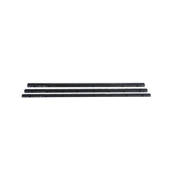
Machine tools often contain components that need controlled movement along a defined path. A cutting head, worktable, or gantry structure may need to move while remaining supported by guides and other machine elements. Rack-and-pinion transmission can provide the driving movement for these assemblies.
In a large machine structure, the rack can be installed along the axis of travel. A rotating gear connected to the drive system engages with the rack and moves the attached assembly. The guide structure carries the moving load, while the rack and gear provide the driving force.
The mechanical arrangement needs to work with the rest of the machine rather than operate independently. Several points influence the design:
CNC machine applications also show why the surrounding mechanical structure matters. A rack can provide the driving movement, but accurate machine operation depends on the rack, gear, guides, mounting surfaces, and control system working together.
Automotive steering provides a different use of the same basic mechanical relationship. Steering input begins as rotational movement, while the road wheels need movement from side to side. A rack-and-pinion arrangement connects these two types of motion within the steering mechanism.
When the steering input rotates the gear, the rack moves laterally. Linkage connected to the rack transfers that movement toward the steering components. The rack therefore acts as the linear element within a system that begins with rotary input.
The design places particular importance on:
Material handling machinery uses rack-and-pinion movement in another way. Automated production equipment may need to move a carrier, platform, or handling assembly along a fixed route. A gear-driven rack can provide the movement needed to position such components within the machine.
In a production environment, the driven part may move horizontally along a gantry or support structure. The rack remains fixed while the gear travels with the moving assembly, or the arrangement can be reversed depending on the machine design.
Material-handling applications can include:
The steering application emphasizes controlled lateral movement, while material handling places greater attention on machine layout, travel path, and integration with surrounding equipment. Both applications show how a toothed rack can provide a direct mechanical connection between rotational input and linear travel.
A Spur Rack And Pinion arrangement remains relevant wherever machinery needs this type of movement and where the rack can be integrated with the available guides, supports, and drive components.
Vertical movement places different demands on a rack-driven mechanism. In lifting equipment, a rack can follow the movement path of a platform while a rotating gear drives the assembly upward or downward. The rack may be fixed to the supporting structure, with the gear moving alongside the platform, or the arrangement can be reversed.
Stage lifts and industrial elevation equipment can use this type of drive where guided movement is required. The rack itself does not replace the supporting guides. Instead, the gear and rack provide the driving movement while the guide structure keeps the platform aligned.
Valve systems use a similar arrangement for a different task. An actuator can rotate a gear, causing the rack to move along a straight path. That movement can operate a valve mechanism connected to the rack. Correct positioning between the actuator, gear, rack, and valve assembly matters because repeated operation can place stress on the contact surfaces.
Moisture, dust, fluid residue, and installation space may also affect component selection. A mechanism inside protected equipment has different maintenance needs from one installed in an exposed industrial area.
Sliding gates and doors need a drive that follows the panel along its opening path. A motor can rotate the gear while a rack attached to the panel converts that rotation into linear travel.
The rack usually follows the route taken by the moving panel. Correct gear height and mounting alignment help maintain steady tooth contact. Rack sections also need to meet cleanly when a longer opening requires more than one section.
Practical design checks include:
A stairlift can use a related arrangement along an inclined guide. The movement path changes, but the mechanical relationship remains based on a rotating gear engaging with a straight rack.
The required movement should be defined before component selection. Travel direction, load, available space, and operating conditions all influence the arrangement.
| Design Factor | What Needs Attention | Application Relevance |
|---|---|---|
| Movement Direction | Horizontal, vertical, or inclined travel | Affects installation |
| Load Condition | Force on the moving assembly | Influences component choice |
| Travel Path | Required movement distance | Determines rack layout |
| Installation Space | Room for rack and gear | Affects positioning |
| Tooth Engagement | Contact between mating teeth | Influences movement |
| Working Environment | Dust, moisture, heat, or residue | Affects maintenance needs |
Alignment deserves particular attention. A rack that is poorly positioned against the gear can create uneven tooth contact. The guides and mounting surfaces also need to hold their positions during operation.
Long travel paths require attention at rack joints. Connected sections should form a continuous tooth path so that the moving gear does not encounter an abrupt change as it passes from one section to another.
A Spur Gear Rack Factory has to produce components that work with a matching gear, not simply a straight bar with teeth. Tooth shape, rack straightness, surface condition, and mounting features can all affect assembly.
Production inspection may cover:
Long rack assemblies require care around connection points. Small differences between sections can influence gear movement after installation.
Application also affects production requirements. A rack intended for a sliding door may face different conditions from one used inside machine equipment or a lifting mechanism. Material selection, surface treatment, and environmental protection can vary with the working setting.
Wear usually develops gradually on contacting and mounting surfaces. Routine inspection can focus on tooth condition, alignment, fasteners, guides, and accumulated contamination.
Useful maintenance checks include:
Maintenance conditions vary with the installation. Outdoor gates may collect moisture and dirt, while machinery used for material processing may accumulate dust or residue around exposed components.
When replacement becomes necessary, checking both mating components can help identify whether wear comes from the rack, gear, alignment, or another part of the assembly. A Spur Gear Rack Factory can use the application requirements to guide component dimensions and matching during production.

© 2025 Zhejiang Yuchen Transmission Technology Co., Ltd.

Transmission Gear And Rack


